109 19.5 Batteries and Fuel Cells

Learning Objectives

By the end of this section, you will be able to:
  • Classify batteries as primary or secondary
  • List some of the characteristics and limitations of batteries
  • Provide a general description of a fuel cell

A battery is an electrochemical cell or series of cells that produces an electric current. In principle, any galvanic cell could be used as a battery. An ideal battery would never run down, produce an unchanging voltage, and be capable of withstanding environmental extremes of heat and humidity. Real batteries strike a balance between ideal characteristics and practical limitations. For example, the mass of a car battery is about 18 kg or about 1% of the mass of an average car or light-duty truck. This type of battery would supply nearly unlimited energy if used in a smartphone, but would be rejected for this application because of its mass. Thus, no single battery is “best” and batteries are selected for a particular application, keeping things like the mass of the battery, its cost, reliability, and current capacity in mind. There are two basic types of batteries: primary and secondary. A few batteries of each type are described next.

Primary Batteries

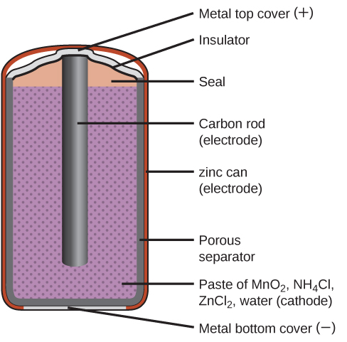
Primary batteries are single-use batteries because they cannot be recharged. A common primary battery is the dry cell (Figure 1). The dry cell is a zinc-carbon battery. The zinc can serves as both a container and the negative electrode. The positive electrode is a rod made of carbon that is surrounded by a paste of manganese(IV) oxide, zinc chloride, ammonium chloride, carbon powder, and a small amount of water. The reaction at the anode can be represented as the ordinary oxidation of zinc:

[latex]\text{Zn}(s)\;{\longrightarrow}\;\text{Zn}^{2+}(aq)\;+\;2\text{e}^{-}\;\;\;\;\;\;\;E_{\text{Zn}^{2+}/\text{Zn}}^{\circ} = -0.7618\;\text{V}[/latex]

The reaction at the cathode is more complicated, in part because more than one reaction occurs. The series of reactions that occurs at the cathode is approximately

[latex]2\text{MnO}_2(s)\;+\;2\text{NH}_4\text{Cl}(aq)\;+\;2\text{e}^{-}\;{\longrightarrow}\;\text{Mn}_2\text{O}_3(s)\;+\;2\text{NH}_3(aq)\;+\;\text{H}_2\text{O}(l)\;+\;2\text{Cl}^{-}[/latex]

The overall reaction for the zinc–carbon battery can be represented as [latex]2\text{MnO}_2(s)\;+\;2\text{NH}_4\text{Cl}(aq)\;+\;\text{Zn}(s)\;{\longrightarrow}\;\text{Zn}^{2+}(aq)\;+\;\text{Mn}_2\text{O}_3(s)\;+\;2\text{NH}_3(aq)\;+\;\text{H}_2\text{O}(l)\;+\;2\text{Cl}^{-}[/latex] with an overall cell potential which is initially about 1.5 V, but decreases as the battery is used. It is important to remember that the voltage delivered by a battery is the same regardless of the size of a battery. For this reason, D, C, A, AA, and AAA batteries all have the same voltage rating. However, larger batteries can deliver more moles of electrons. As the zinc container oxidizes, its contents eventually leak out, so this type of battery should not be left in any electrical device for extended periods.

A diagram of a cross section of a dry cell battery is shown. The overall shape of the cell is cylindrical. The lateral surface of the cylinder, indicated as a thin red line, is labeled “zinc can (electrode).” Just beneath this is a slightly thicker dark grey surface that covers the lateral surface, top, and bottom of the battery, which is labeled “Porous separator.” Inside is a purple region with many evenly spaced small darker purple dots, labeled “Paste of M n O subscript 2, N H subscript 4 C l, Z n C l subscript 2, water (cathode).” A dark grey rod, labeled “Carbon rod (electrode),” extends from the top of the battery, leaving a gap of less than one-fifth the height of the battery below the rod to the bottom of the cylinder. A thin grey line segment at the very bottom of the cylinder is labeled “Metal bottom cover (negative).” The very top of the cylinder has a thin grey surface that curves upward at the center over the top of the carbon electrode at the center of the cylinder. This upper surface is labeled “Metal top cover (positive).” A thin dark grey line just below this surface is labeled “Insulator.” Below this, above the purple region, and outside of the carbon electrode at the center is an orange region that is labeled “Seal.”
Figure 1. The diagram shows a cross section of a flashlight battery, a zinc-carbon dry cell.

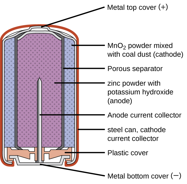
Alkaline batteries (Figure 2) were developed in the 1950s partly to address some of the performance issues with zinc–carbon dry cells. They are manufactured to be exact replacements for zinc-carbon dry cells. As their name suggests, these types of batteries use alkaline electrolytes, often potassium hydroxide. The reactions are

[latex]\begin{array}{lr @{{}\longrightarrow{}} ll} \text{anode:} & \text{Zn}(s)\;+\;2\text{OH}^{-}(aq) & \longrightarrow \text{ZnO}(s)\;+\;\text{H}_2\text{O}(l)\;+\;2\text{e}^{-} & E_{\text{anode}}^{\circ} = -1.28\;\text{V} \\[0.5em] \text{cathode:} & 2\text{MnO}_2(s)\;+\;\text{H}_2\text{O}(l)\;+\;2\text{e}^{-} & \longrightarrow \text{Mn}_2\text{O}_3(s)\;+\;2\text{OH}^{-}(aq) & E_{\text{cathode}}^{\circ} = +0.15\;\text{V} \\[0.5em] \hline \\[-0.25em] \text{overall:} & \text{Zn}(s)\;+\;2\text{MnO}_2(s) & \longrightarrow \text{ZnO}(s)\;+\;\text{Mn}_2\text{O}_3(s) & E_{\text{cell}}^{\circ} = +1.43\;\text{V} \end{array}[/latex]

An alkaline battery can deliver about three to five times the energy of a zinc-carbon dry cell of similar size. Alkaline batteries are prone to leaking potassium hydroxide, so these should also be removed from devices for long-term storage. While some alkaline batteries are rechargeable, most are not. Attempts to recharge an alkaline battery that is not rechargeable often leads to rupture of the battery and leakage of the potassium hydroxide electrolyte.

A diagram of a cross section of an alkaline battery is shown. The overall shape of the cell is cylindrical. The lateral surface of the cylinder, indicated as a thin red line, is labeled “Outer casing.” Just beneath this is a thin, light grey surface that covers the lateral surface and top of the battery. Inside is a blue region with many evenly spaced small darker dots, labeled “M n O subscript 2 (cathode).” A thin dark grey layer is just inside, which is labeled “Ion conducting separator.” A purple region with many evenly spaced small darker dots fills the center of the battery and is labeled “ zinc (anode).” The very top of the battery has a thin grey curved surface over the central purple region. The curved surface above is labeled “Positive connection (plus).” At the base of the battery, an orange structure, labeled “Protective cap,” is located beneath the purple and blue central regions. This structure holds a grey structure that looks like a nail with its head at the bottom and pointed end extending upward into the center of the battery. This nail-like structure is labeled “Current pick up.” At the very bottom of the battery is a thin grey surface that is held by the protective cap. This surface is labeled “Negative terminal (negative).”
Figure 2. Alkaline batteries were designed as direct replacements for zinc-carbon (dry cell) batteries.

Secondary Batteries

Secondary batteries are rechargeable. These are the types of batteries found in devices such as smartphones, electronic tablets, and automobiles.

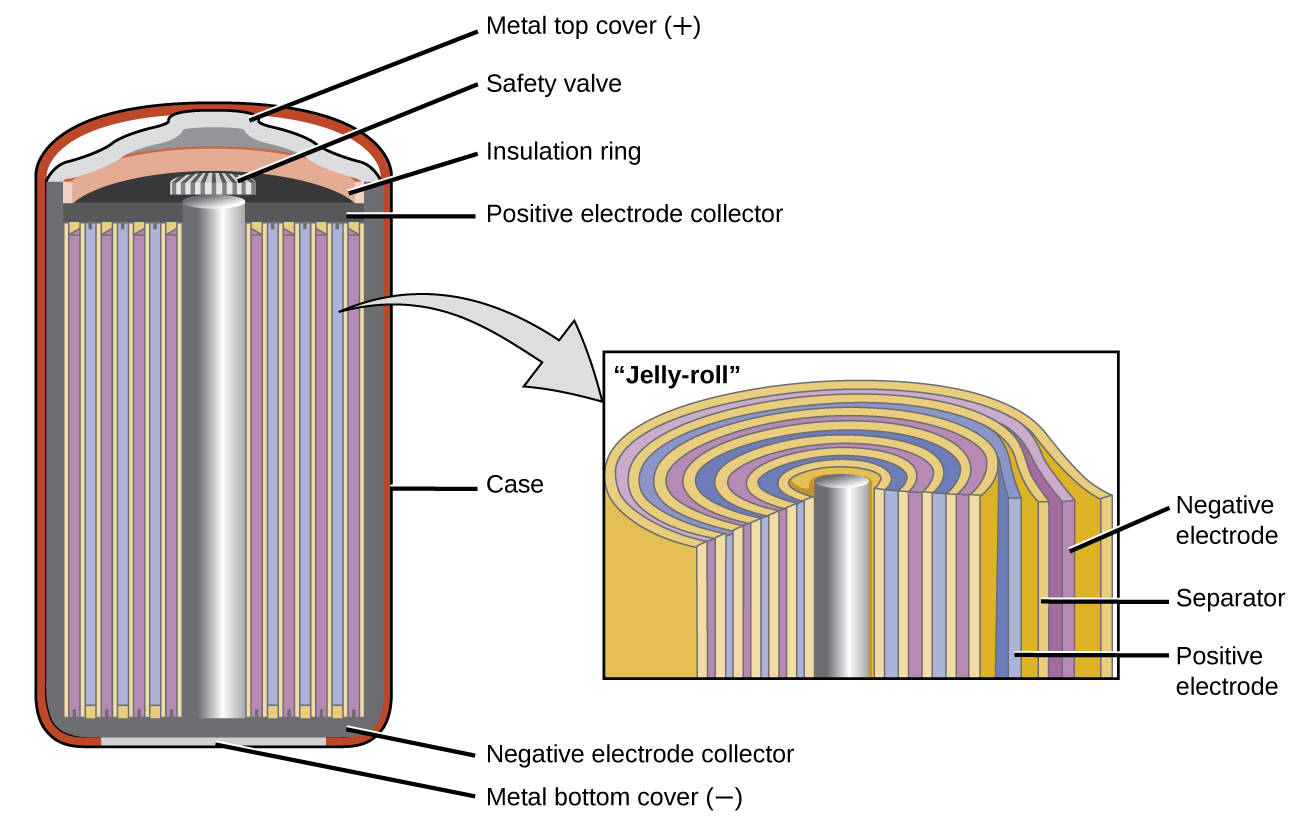
Nickel-cadmium, or NiCd, batteries (Figure 3) consist of a nickel-plated cathode, cadmium-plated anode, and a potassium hydroxide electrode. The positive and negative plates, which are prevented from shorting by the separator, are rolled together and put into the case. This is a “jelly-roll” design and allows the NiCd cell to deliver much more current than a similar-sized alkaline battery. The reactions are

[latex]\begin{array}{lr @{{}\longrightarrow{}} l} \text{anode:} & \text{Cd}(s)\;+\;2\text{OH}^{-}(aq) & \longrightarrow \text{Cd(OH)}_2(s)\;+\;2\text{e}^{-} \\[0.5em] \text{cathode:} & \text{NiO}_2(s)\;+\;2\text{H}_2\text{O}(l)\;+\;2\text{e}^{-} & \longrightarrow \text{Ni(OH)}_2(s)\;+\;2\text{OH}^{-}(aq) \\[0.5em] \hline \\[-0.25em] \text{overall:} & \text{Cd}(s)\;+\;\text{NiO}_2(s)\;+\;2\text{H}_2\text{O}(l) & \longrightarrow \text{Cd(OH)}_2(s)\;+\;\text{Ni(OH)}_2(s) \end{array}[/latex]

The voltage is about 1.2 V to 1.25 V as the battery discharges. When properly treated, a NiCd battery can be recharged about 1000 times. Cadmium is a toxic heavy metal so NiCd batteries should never be opened or put into the regular trash.

A diagram is shown of a cross section of a nickel cadmium battery. This battery is in a cylindrical shape. An outer red layer is labeled “case.” Just inside this layer is a thin, dark grey layer which is labeled at the bottom of the cylinder as “Negative electrode collector.” A silver rod extends upward through the center of the battery, which is surrounded by alternating layers, shown as vertical repeating bands, of yellow, purple, yellow, and blue. A slightly darker grey narrow band extends across the top of these alternating bands, which is labeled “Positive electrode collector.” A thin light grey band appears at the very bottom of the cylinder, which is labeled “Metal bottom cover (negative).” A small grey and white striped rectangular structure is present at the top of the central silver cylinder, which is labeled “Safety valve.” Above this is an orange layer that curves upward over the safety valve, which is labeled “Insulation ring.” Above this is a thin light grey layer that projects upward slightly at the center, which is labeled “Metal top cover (plus).” A light grey arrow points to a rectangle to the right that illustrates the layers at the center of the battery under magnification. From the central silver rod, the layers shown repeat the alternating pattern yellow, blue, yellow, and purple three times, with a final yellow layer covering the last purple layer. The outermost purple layer is labeled “Negative electrode.” The yellow layer beneath it is labeled “Separator.” The blue layer just inside is labeled “Positive electrode.”
Figure 3. NiCd batteries use a “jelly-roll” design that significantly increases the amount of current the battery can deliver as compared to a similar-sized alkaline battery.

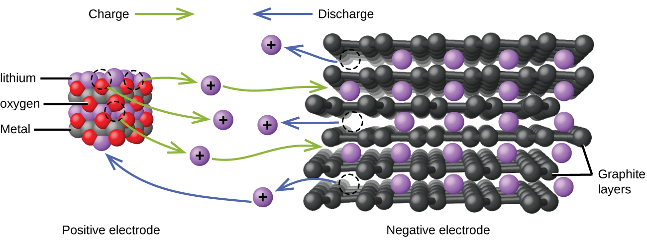
Lithium ion batteries (Figure 4) are among the most popular rechargeable batteries and are used in many portable electronic devices. The reactions are

[latex]\begin{array}{lr @{{}\leftrightharpoons{}} l} \text{anode:} & \text{LiCoO}_2 & \leftrightharpoons \text{Li}_{x\;-\;1}\text{CoO}_2\;+\;x\;\text{Li}^{+}\;+\;x\;\text{e}^{-} \\[0.5em] \text{cathode:} & x\;\text{Li}^{+}\;+\;x\;\text{e}^{-}\;+\;x\;\text{C}_6 & \leftrightharpoons x\;\text{LiC}_6 \\[0.5em] \hline \\[-0.25em] \text{overall:} & \text{LiCoO}_2\;+\;x\;\text{C}_6 & \leftrightharpoons \text{Li}_{x\;-\;1}\text{CoO}_2\;+\;x\;\text{LiC}_6 \end{array}[/latex]

With the coefficients representing moles, x is no more than about 0.5 moles. The battery voltage is about 3.7 V. Lithium batteries are popular because they can provide a large amount current, are lighter than comparable batteries of other types, produce a nearly constant voltage as they discharge, and only slowly lose their charge when stored.

This figure shows a model of the flow of charge in a lithium ion battery. At the left, an approximately cubic structure formed by alternating red, grey, and purple spheres is labeled below as “Positive electrode.” The purple spheres are identified by the label “lithium.” The grey spheres are identified by the label “Metal.” The red spheres are identified by the label “oxygen.” Above this structure is the label “Charge” followed by a right pointing green arrow. At the right is a figure with layers of black interconnected spheres with purple spheres located in gaps between the layers. The black layers are labeled “Graphite layers.” Below the purple and black structure is the label “Negative electrode.” Above is the label “Discharge,” which is preceded by a blue arrow which points left. At the center of the diagram between the two structures are six purple spheres which are each labeled with a plus symbol. Three curved green arrows extend from the red, purple, and grey structure to each of the three closest purple plus labeled spheres. Green curved arrows extend from the right side of the upper and lower of these three purple plus labeled spheres to the black and purple layered structure. Three blue arrows extend from the purple and black layered structure to the remaining three purple plus labeled spheres at the center of the diagram. The base of each arrow has a circle formed by a dashed curved line in the layered structure. The lowest of the three purple plus marked spheres reached by the blue arrows has a second blue arrow extending from its left side which points to a purple sphere in the purple, green, and grey structure.
Figure 4. In a lithium ion battery, charge flows between the electrodes as the lithium ions move between the anode and cathode.

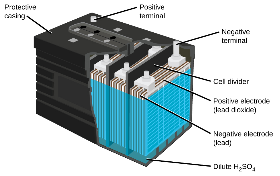
The lead acid battery (Figure 5) is the type of secondary battery used in your automobile. It is inexpensive and capable of producing the high current required by automobile starter motors. The reactions for a lead acid battery are

[latex]\begin{array}{lr @{{}\longrightarrow{}} l} \text{anode:} & \text{Pb}(s)\;+\;\text{HSO}_4^{\;\;-}(aq) & \longrightarrow \text{PbSO}_4(s)\;+\;\text{H}^{+}(aq)\;+\;2\text{e}^{-} \\[0.5em] \text{cathode:} & \text{PbO}_2(s)\;+\;\text{HSO}_4^{\;\;-}(aq)\;+\;3\text{H}^{+}(aq)\;+\;2\text{e}^{-} & \longrightarrow \text{PbSO}_4(s)\;+\;2\text{H}_2\text{O}(l) \\[0.5em] \hline \\[-0.25em] \text{overall:} & \text{Pb}(s)\;+\;\text{PbO}_2(s)\;+\;2\text{H}_2\text{SO}_4(aq) & \longrightarrow 2\text{PbSO}_4(s)\;+\;2\text{H}_2\text{O}(l) \end{array}[/latex]

Each cell produces 2 V, so six cells are connected in series to produce a 12-V car battery. Lead acid batteries are heavy and contain a caustic liquid electrolyte, but are often still the battery of choice because of their high current density. Since these batteries contain a significant amount of lead, they must always be disposed of properly.

A diagram of a lead acid battery is shown. A black outer casing, which is labeled “Protective casing” is in the form of a rectangular prism. Grey cylindrical projections extend upward from the upper surface of the battery in the back left and back right corners. At the back right corner, the projection is labeled “Positive terminal.” At the back right corner, the projection is labeled “Negative terminal.” The bottom layer of the battery diagram is a dark green color, which is labeled “Dilute H subscript 2 S O subscript 4.” A blue outer covering extends upward from this region near the top of the battery. Inside, alternating grey and white vertical “sheets” are packed together in repeating units within the battery. The battery has the sides cut away to show three of these repeating units which are separated by black vertical dividers, which are labeled as “cell dividers.” The grey layers in the repeating units are labeled “Negative electrode (lead).” The white layers are labeled “Postive electrode (lead dioxide).”
Figure 5. The lead acid battery in your automobile consists of six cells connected in series to give 12 V. Their low cost and high current output makes these excellent candidates for providing power for automobile starter motors.

Fuel Cells

A fuel cell is a device that converts chemical energy into electrical energy. Fuel cells are similar to batteries but require a continuous source of fuel, often hydrogen. They will continue to produce electricity as long as fuel is available. Hydrogen fuel cells have been used to supply power for satellites, space capsules, automobiles, boats, and submarines (Figure 6).

A diagram is shown of a hydrogen fuel cell. At the center is a narrow vertical rectangle which is shaded tan and labeled “Electrolyte.” To the right is a slightly wider and shorter purple rectangle which is labeled “Cathode.” To the left is a rectangle of the same size which is labeled “Anode.” Grey rectangles that are slightly wider and longer are at the right and left sides, attached to the purple and blue rectangles. On the right side, a white region overlays the grey rectangle. This white region provides a pathway for O subscript 2 to enter at the upper left, move inward and along the interface with the purple region, and exit to the lower right. A similar pathway overlays the grey region on the left, allowing a pathway for the entry of H subscript 2 from the upper right along the interface with the blue rectangle, allowing for the exit of H subscript 2 O out to the lower left of the diagram. Black line segments extend upward from the blue and purple regions. These line segments are connected by a horizontal segment that has a yellow zig zag shape at the center. This shape is labeled “Electric power.” At the left of the diagram, in the upper left white region, 2 H subscript 2 is followed by an arrow that points right and down to H subscript 2. An arrow points right into the blue region to H subscript 2 O. A curved arrow point up to e superscript negative. Another e superscript negative is placed nearby and has an upward pointing arrow extending up to the left of the line segment extending from the purple region. A second arrow points upward along this segment with the label “e superscript negative” to its left. A curved arrow extends down and to the left from the H subscript 2 O into the white region. A second H subscript 2 O is shown below the first in the blue region repeating the arrow patterns established above. At the lower left, an arrow points left, to the exit of the white region. At the tip of this arrow is the label “2 H subscript 2 O.” In the central brown region, O superscript 2 negative is listed twice with arrows pointing left, to the H subscript 2 O formulas in the blue region. At the upper right, O subscript 2 is shown with an arrow pointing left and down to O subscript 2 in the white region. An arrow points left from this point into the purple region. From the tip of the arrow, two arrows point to the two O subscript 2 negative structures in the brown central region. An arrow, labeled “e superscript negative” points downward to the right of the line segment above the purple region. A second arrow extends down into the purple region, pointing to e superscript negative. Three additional e superscript negative symbols appear nearby. An arrow extends from them to the point where the arrows meet in the purple region.
Figure 6. In this hydrogen fuel-cell schematic, oxygen from the air reacts with hydrogen, producing water and electricity.

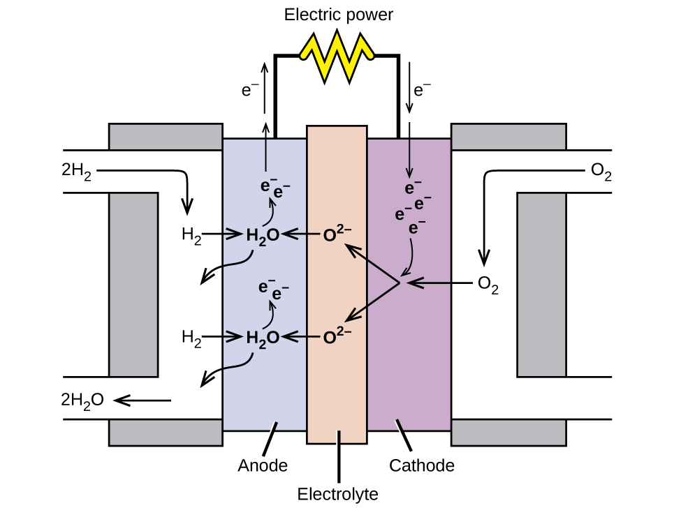
In a hydrogen fuel cell, the reactions are

[latex]\begin{array}{lr @{{}\longrightarrow{}} l} \text{anode:} & 2\text{H}_2\;+\;2\text{O}^{2-} & \longrightarrow 2\text{H}_2\text{O}\;+\;4\text{e}^{-} \\[0.5em] \text{cathode:} & \text{O}_2\;+\;4\text{e}^{-} & \longrightarrow 2\text{O}^{2-} \\[0.5em] \hline \\[-0.25em] \text{overall:} & 2\text{H}_2\;+\;\text{O}_2 & \longrightarrow 2\text{H}_2\text{O} \end{array}[/latex]

The voltage is about 0.9 V. The efficiency of fuel cells is typically about 40% to 60%, which is higher than the typical internal combustion engine (25% to 35%) and, in the case of the hydrogen fuel cell, produces only water as exhaust. Currently, fuel cells are rather expensive and contain features that cause them to fail after a relatively short time.

Key Concepts and Summary

Batteries are galvanic cells, or a series of cells, that produce an electric current. When cells are combined into batteries, the potential of the battery is an integer multiple of the potential of a single cell. There are two basic types of batteries: primary and secondary. Primary batteries are “single use” and cannot be recharged. Dry cells and (most) alkaline batteries are examples of primary batteries. The second type is rechargeable and is called a secondary battery. Examples of secondary batteries include nickel-cadmium (NiCd), lead acid, and lithium ion batteries. Fuel cells are similar to batteries in that they generate an electrical current, but require continuous addition of fuel and oxidizer. The hydrogen fuel cell uses hydrogen and oxygen from the air to produce water, and is generally more efficient than internal combustion engines.

Chemistry End of Chapter Exercises

  1. What are the desirable qualities of an electric battery?
  2. List some things that are typically considered when selecting a battery for a new application.
  3. Consider a battery made from one half-cell that consists of a copper electrode in 1 M CuSO4 solution and another half-cell that consists of a lead electrode in 1 M Pb(NO3)2 solution.

    (a) What are the reactions at the anode, cathode, and the overall reaction?

    (b) What is the standard cell potential for the battery?

    (c) Most devices designed to use dry-cell batteries can operate between 1.0 and 1.5 V. Could this cell be used to make a battery that could replace a dry-cell battery? Why or why not.

    (d) Suppose sulfuric acid is added to the half-cell with the lead electrode and some PbSO4(s) forms. Would the cell potential increase, decrease, or remain the same?

  4. Consider a battery with the overall reaction: [latex]\text{Cu}(s)\;+\;2\text{Ag}^{+}(aq)\;{\longrightarrow}\;2\text{Ag}(s)\;+\;\text{Cu}^{2+}(aq)[/latex].

    (a) What is the reaction at the anode and cathode?

    (b) A battery is “dead” when it has no cell potential. What is the value of Q when this battery is dead?

    (c) If a particular dead battery was found to have [Cu2+] = 0.11 M, what was the concentration of silver ion?

  5. An inventor proposes using a SHE (standard hydrogen electrode) in a new battery for smartphones that also removes toxic carbon monoxide from the air:
    [latex]\begin{array}{lr @{{}\longrightarrow{}} ll} \text{Anode:} & \text{CO}(g)\;+\;\text{H}_2\text{O}(l) & \longrightarrow \text{CO}_2(g)\;+\;2\text{H}^{+}(aq)\;+\;2\text{e}^{-} & E_{\text{anode}}^{\circ} = -0.53\;\text{V} \\[0.5em] \text{Cathode:} & 2\text{H}^{+}(aq)\;+\;2\text{e}^{-} & \longrightarrow \text{H}_2(g) & E_{\text{cathode}}^{\circ} = 0.00\;\text{V} \\[0.5em] \hline \\[-0.25em] \text{Overall:} & \text{CO}(g)\;+\;\text{H}_2\text{O}(l) & \longrightarrow \text{CO}_2(g)\;+\;\text{H}_2(g) & E_{\text{cell}}^{\circ} = +0.53\;\text{V} \end{array}[/latex]

    Would this make a good battery for smartphones? Why or why not?

  6. Why do batteries go dead, but fuel cells do not?
  7. Explain what happens to battery voltage as a battery is used, in terms of the Nernst equation.
  8. Using the information thus far in this chapter, explain why battery-powered electronics perform poorly in low temperatures.

Glossary

alkaline battery
primary battery that uses an alkaline (often potassium hydroxide) electrolyte; designed to be an exact replacement for the dry cell, but with more energy storage and less electrolyte leakage than typical dry cell
battery
galvanic cell or series of cells that produces a current; in theory, any galvanic cell
dry cell
primary battery, also called a zinc-carbon battery; can be used in any orientation because it uses a paste as the electrolyte; tends to leak electrolyte when stored
fuel cell
devices that produce an electrical current as long as fuel and oxidizer are continuously added; more efficient than internal combustion engines
lead acid battery
secondary battery that consists of multiple cells; the lead acid battery found in automobiles has six cells and a voltage of 12 V
lithium ion battery
very popular secondary battery; uses lithium ions to conduct current and is light, rechargeable, and produces a nearly constant potential as it discharges
nickel-cadmium battery
(NiCd battery) secondary battery that uses cadmium, which is a toxic heavy metal; heavier than lithium ion batteries, but with similar performance characteristics
primary battery
single-use nonrechargeable battery
secondary battery
battery that can be recharged

Solutions

Answers to Chemistry End of Chapter Exercises

2. Considerations include: cost of the materials used in the battery, toxicity of the various components (what constitutes proper disposal), should it be a primary or secondary battery, energy requirements (the “size” of the battery/how long should it last), will a particular battery leak when the new device is used according to directions, and its mass (the total mass of the new device).

4. (a) [latex]\begin{array}{lr @{{}\longrightarrow{}} ll} \text{anode:} & \text{Cu}(s) & \longrightarrow \text{Cu}^{2+}(aq)\;+\;2\text{e}^{-} & E_{\text{anode}}^{\circ} = 0.34\;\text{V} \\[0.5em] \text{cathode:} & 2\;\times\;(\text{Ag}^{+}(aq)\;+\;\text{e}^{-} & \longrightarrow \text{Ag}(s)) & E_{\text{cathode}}^{\circ} = 0.7996\;\text{V} \end{array}[/latex]

(b) 3.5 × 10¹⁵

(c) 5.6 × 10⁻⁹M

6. Batteries are self-contained and have a limited supply of reagents to expend before going dead. Alternatively, battery reaction byproducts accumulate and interfere with the reaction. Because a fuel cell is constantly resupplied with reactants and products are expelled, it can continue to function as long as reagents are supplied.

8. Ecell, as described in the Nernst equation, has a term that is directly proportional to temperature. At low temperatures, this term is decreased, resulting in a lower cell voltage provided by the battery to the device—the same effect as a battery running dead.

License

Icon for the Creative Commons Attribution 4.0 International License

College of Western Idaho General Chemistry: CHEM 111 & 112 Copyright © 2016 by Rice University is licensed under a Creative Commons Attribution 4.0 International License, except where otherwise noted.

Share This Book